CS 5113 and 4113 Fall 19
This is the web page for Operation Systems Theory at the University of Oklahoma.
Project 1
Operating Systems Theory (Fall 2019)
tl;dr
- 10/31 Alpha deadline; choose your team members and programming language.
- 11/12 Test Integration; create two unique test case (graph architectures and starting nodes) and the message that will likely be sent.
- 11/26 Submit code and project.
Introduction
In phase 1 of the project, you learned how to use docker to create a distributed network and use gRPC to communicate between nodes. As we’ve studied, production distributed systems can have a variety of exotic data structures. No matter the use case, it is often important for a node to deliver, nee broadcast, a message to all other nodes in the system. To do this efficiently, networks will discover the best – most efficient – method of routing the messages. Discovery of these links is called the minimum spanning tree.
In this project, you will implement a completely decentralized minimum spanning tree based on a slight modification to one of the earliest such algorithms proposed by Gallager, Humblet, and Spira. Below we discuss the minimum spanning tree, and then we give a break down of the distributed implementation you will use for the project. We then give the requirements and deadline for the project.
MST
Given a graph $G = (N,E) $ with $|N|$ nodes and $|E|$ edges where each edge is undirected and has a unique edge weight ($w(e)$ for $e \in E$). Minimum spanning tree is a subgraph with no cycles where all nodes are connected and the sum of the connecting edges is minimized. \(\sum_{e \in E} e\)
There two important properties that follow this definition.
- If each edge has a distinct weight then there will be only one, unique minimum spanning tree.
- If the minimum cost edge $e$ of a graph is unique, then this edge is included in any MST.
These properties form the core of the two popular non-distributed MST algorithms: Prim’s algorithm and Kruskal’s algorithm.
In Prim’s algorithm, a single start node is selected and the smallest edge that connects a new node is iterativley selected so that is does not create a cycle.
In Kruskals algorithm, the program starts with all nodes being an independent graph and iterativley selects the smallest edge that does not create a spanning tree. This continues until a minimum spanning tree must be created.
Each of these algorithms assumes global knowledge of all nodes and edges in the system. In this project, we implement a distributed MST algorithm, where nodes only have information about their neighbors and must act independently. Messages are passed between nodes following an agreed upon protocol until the MST is discovered and an ‘END’ message is sent on it’s path to code. We discuss the algorithm in more detail below. Because the expected system setup is slightly different for this project, you also need to carefully read the following system requirements. We describe the program/system setup below.
Poject 1 Setup
The table below describe the minimum files that will need to be submitted. Some files are provided, but you are welcomed to provide more files as needed.
| File Name | Description | Responsibility |
|---|---|---|
| config.ini | The file that is used to desrcibe the network and edge weights. | Provided |
| network_generator.py | Python script to create a docker-compose.yml file of arbitrary size. | Provided |
| gallager.proto | The interface description file (IDL) that describes the protocol. | You |
| Dockerfile | The Dockerfile is a script that describes how to compile and build the system needed for the algorithm. | You |
| docker-compose.yml | This file is used to create the connected network of docker docker instances. | You |
| node.py | This file (or similar) is the entry point of the distributed mnst program. | You |
| README | This file describes how to build, run and interpret results; Also describes the algorithm used and effort used ot build the program. | You |
| COLLABORATORS | Describes the resources (people and otherwise) who contributed to the project. | You |
In the project description that follows, I will assume you are using the latest version of Python. If you are using a different programming language please translate the directions as appropriate. If the directions are not clear please come see me in office hours.
Setting up the program
Before running the program, you need to develop a test scenario.
That is you should decide on an appropriate test architecture.
We expect you to create a graph with 5-10 nodes and unique undirected edge weights.
You should then create a config.ini file that describes this architecture.
config.ini
We’ve attached an example config.ini.
The configuration file is ONLY read by the coordinator.
It contains two main sections: the overall architecture size and information about the links.
Under the section header are key value description of the nodes and links.
In the first section header has the term [gallager], the first key value is is the term node and the total number of nodes in the system, not including the coordinator.
Then the key port is followed by the port number that will be used by all server and clients in the system.
(It is fine to keep a that same port across the system and not rely on the config file.)
The second section has the header [links] and contains the topology of the network listed as an adjancy matrix.
Each row has a key that is the name of the node. This is assumed to be of the form nodeX where X is some integer.
The value each key is an integer weight integer value separated separated by a pipe symbol (the symbol | above the enter key).
The config file can be easily read using the configparser in Python.
network_generator.py
The netwwork_generator is a small file we created to build arbitrary sized network configuration files with docker-compose.
You can do this manually but this program is provided as a convenience.
To use it, you will need to install the click package pip3 install click and requires Python 3.6+.
To use the program for a topology of six machines, run for following command:
python3 network_generator.py --count 6 --coordinator coordinator --prefix node > docker-compose.yml
Note, if you are using a shared machine and docker, such as the gpel* machines, you will want to customize the names of the machines to avoid name space collisions.
To do this, you can use your 4x4 or other identifier to prefix the machines --coordinator bond0007coordinator --prefix bond007node .
Starting the program
Calling the docker-compose up --build should build two sets of nodes the Coordinator and the network nodes and run the program.
The node.py file in the coordinator should read the config.ini file and pass the parameters to each of the awating nodes in the system.
The node.py file should only send a list of the nodes neighbors weights to each node in the system.
Each node should only be give its neighbor information and port number, they should not know about any other node in the system.
Given the example configuration in provided config.ini file, node0 should only be passed [node1, node2, node5] and [2,6,3].
This should be supplied via a gRPC message.
Below is an example protofile setup that can be created for this message.
// ...

service Gallager {
  Begin(BeginRequest) returns (MsgAck) {}
  // ...
}

// ...

// The Message to get the process started
message BeginRequest {
  // Node name that is receiving the message
  string nodename = 1;

  // Neighbors of the nodes
  // This is a string of node names
  repeated string neighbors = 2;

  // Weights of links corresponding to neighbors
  repeated int32 weights = 3;
}

//...
NodeStates and LinkStatus
In the dmst algorithm there are a few node states and link status. Before discussing the algoorithm we discuss there here.
Initially each node is in ‘sleeping’ state where it is doing nothing unless it is activated on receipt on some protocol message from neighboring node or has been awakened via an external trigger. Other two states that a node could be in are ‘find’ and ‘found’. When a node is in ‘find’ state, it tries to find the least weighted outgoing edge from it to any other MST fragments not part of the MST fragment of which this node is a part. Otherwise, at all other times, it is in ‘found’ state.
The variable link-status describes each nodes neighboring links. The links can have three states, ‘basic’, ‘branch’ or ‘rejected’. A link that has not yet been processed is labeled ‘basic’, if it has been processed and has been accepted to be part of MST by the remote node at the other end, or if the remote node has accepted the request to include it as a link in MST, the status becomes ‘branch’, otherwise if during test phase if the link is found out to create a cycle in the MST fragment, the status becomes ‘rejected’. All links are initialized to the ‘basic’ state.
Additional attributes
The variable ‘fragment-level’ is initialized for every node to 0. Its value might increment as the algorithm proceeds depending on responses from neighbors connected to it to ‘connect’ requests.
The variable ‘fragment-ID’ is the weight of the ‘core-edge’ link of the current MST-fragment. It essentially becomes the unique ID of the whole MST fragment that helps in determining whether a link forms a cycle in this fragment or not.
MsgTypes
Below we discuss the messages that are send between the system nodes.
Begin: A message send from the coordinator to all the nodes in the system. This passes neighbor and weight information to each node to start the algorithm.
Connect: This message is sent by a node or a MST fragment to join into another MST fragment/node. The message also contains the node’s current fragment level. This message is only sent across the least weighted outgoing edge of the MST fragment, or the least weighted edge of a node that just woke up and was in the ‘sleeping’ state until now.
Initiate: When a new ‘core’ edge is formed as a result of two nodes sending ‘Connect’ to each other on the common link, they send outwards on all edges going away from the core an ‘initiate’ message. This message contains the new ‘fragment-level’ as well as ‘fragment-ID’ along with the ‘node-state’ (i.e. ‘find’ or ‘found’) so that all the other nodes in the MST fragment update their node variables and any new fragment waiting to join-in knows if they must initiate the minimum outgoing edge search or not.
Report: This is message generated in response to ‘initiate’ message from the core nodes. This ‘report’ message contains the ‘weight’ of the least weighted outgoing edge of the subtree of the MST fragment rooted at this node to be sent inwards towards the core nodes. After sending ‘report’ message, a node changes its state from ‘find’ to ‘found’ indicating that it’s edge search process has now finished.
Change Core: Once the ‘core’ nodes receive ‘report’ message, they know what part of the MST fragment contains the least weighted outgoing edge, they send the ‘change core’ message along the path from the ‘core’ node towards this outgoing edge (only) so that all nodes along this route change their ‘path to core’ link to this least weighted outgoing edge.
Link Test Probe Message/Reply: When a node is in ‘find’ state as a result of receipt of ‘initiate’ message, it sends out a ‘link-test-probe’ message on links that are in ‘basic’ state from least weighted links and upwards one by one. This message contains ‘fragment-level’ and ‘fragment-ID’ of the sending node. The receiving node checks its own ‘fragment-ID’, if the ‘fragment-ID’ is same, it sends back a REJECT reply to the sender node. If the ‘fragment-ID’ is different and the receiving node’s ‘fragment-level’ is higher or equal to the value received, it sends back a ‘ACCEPT’ validating that this edge is a valid outgoing edge from the sender node to this MST fragment/node. Otherwise, it just delays the response until the receiving node’s ‘fragment-level’ reaches at least as high as the value contained in the ‘test-link-probe’ message.
Gallahger et al.
Note:the explaination in this document is no substitute for reading the original paper. It is expected that you will read the paper before starting the project.
The distributed minimum weight spanning tree algorithm begins with an initial WakeUp message. The coordinator can choose a single node to receive the wake up message.
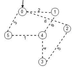
Let me show how one way the algorithm works using the sample graph given in the config.ini above. Without any loss of generality let us assume that the coordinator sends the WakeUp message to ‘node0’, the node to awaken initially.
Any node that awakes, regardless of what caused it i.e. before processing any incoming message that caused it to wake up does the following – it picks the least weighted edge, changes the link-state to ‘branch’ from ‘basic’, sets ‘fragment-level’ to 0, node state to ‘found’ and sends a ‘connect’ message on that link. In this example, node 0 picks link (0-1) and sends a connect request towards node 1.
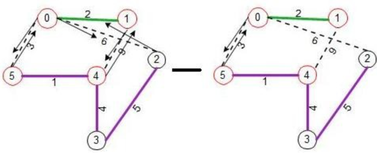
When node 1 receives the connect request, it wakes up and follow the same wakeup routine explained above. Both node 0 and 1, now knows that they did a ‘connect’ on the common edge, they know link (0-1) is the new ‘core’ of the fragment containing nodes {0, 1}. Both these nodes set ‘fragment-level’ to 1 and ‘fragment-ID’ to 2. ‘Fragment-ID is always the weight of the ‘core’ edge of the fragment. The figure below shows the state of the graph after nodes 0 and 1 have formed a fragment, nodes 0 and 1 knows that they are part of the ‘core’ edge and they are shown in red circles.
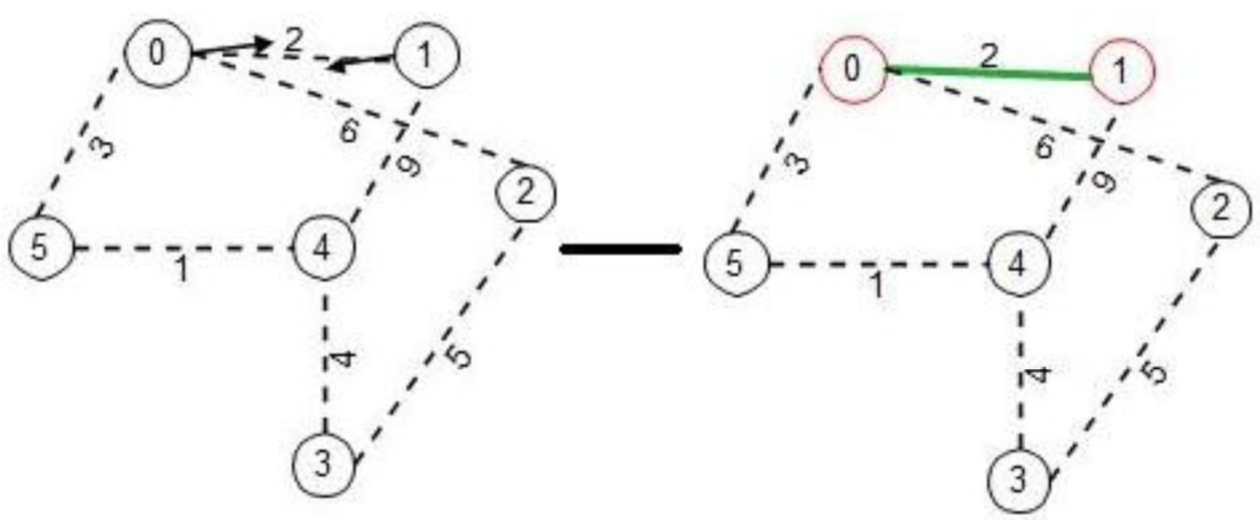
When the ‘connect’ phase is over, each node next to the ‘core’ edge sends an ‘initiate’ message to the nodes outwards from the ‘core’ nodes. As the message traverse, the nodes change their state from ‘found’ to ‘find’.
Whenever any node is in ‘find’ state, it starts sending ‘link-test- probes’ to any links that are in ‘basic’ state starting from one with least weight. In this example, node 0 sends a test-probe on link (0-5) and asynchronously and independently, node 1 sends a test-probe on link (1-4).
Receipt of these test-probes awakes nodes 4 and 5, they do their own wakeup algorithm mentioned earlier, in the process forming another MST fragment containing nodes {4, 5}, while during the whole process queuing the test-probe to be processed after wakeup phase is over.
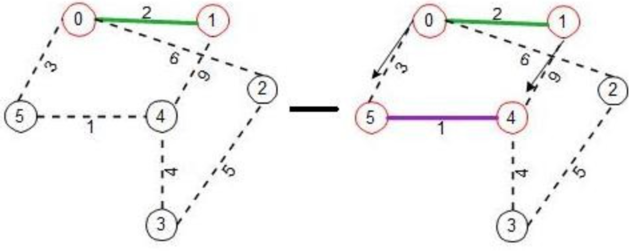
In this process the new fragment sets the ‘fragment-level’ to 1 and ‘fragment-ID’ to 1. Now they both can process the pending test-probes, sees that the fragment-IDs are different and levels are equal, hence they both send back ‘ACCEPT’ to these nodes. Nodes 4 and 5 sends their own ‘initiate’ messages to nodes in their fragments, which in turn makes them test their own ‘basic’ edges for outgoing edge test using ‘link-test-probes’. In the meantime node 0 sends the ‘link-test-probe’ on edge (0-2) which in turn wakes node 2 up from ‘sleeping’ state. Node 2 does its wakeup procedure, which in turn makes it send ‘connect’ to node 3.
Now this wakes node 3. In fact node 3 could have been woken up from ‘link-test-probe’ sent by node 4 but the ordering does not matter. All this is happening asynchronously and independently. Node 3 does a connect towards node 4, which node 4 immediately accepts as it is coming from a lower level fragment. It indicates the ‘connect’ acceptance by sending to node 3, ‘initiate’ message with parameters 1, 1 and ‘find’ for ‘fragment-level’ and ‘fragment-ID’ and ‘node-state’.
Node 3 now processes the ‘connect’ request from node 2, accepts it as the request is coming from a lower level fragment by sending ‘initiate’ to node 2 with arguments 1 and 1. Hence node 2 also becomes part of the MST fragment connected to node 3. All along these processes, nodes keep track of ‘path-to-core’ link to know the path back to the ‘core’ edge. Node 2 for instance knows edge (2-3) is the ‘path-to-core’ link because thats where the ‘initiate’ message came as response to ‘connect’.
ll along this process, nodes process their own ‘link-test- probes’ and sent back appropriate responses REJECT/ACCEPT. Node 2 sends back ACCEPT to ‘link-test-probe’ from node 0 as the ‘fragment-ID’s are different.
Nodes combine all the ‘link-test-responses’ to decide upon the least weighted outgoing edge from their MST fragments. Node 0 and node 1 exchange their reports, making both nodes know that edge (0-5) is the least weighted edge for their fragment. Once the ‘report’ messages reaches ‘core’ nodes and they have been exchanged among both core nodes, they send ‘change-core’ along this path. The passage of ‘change-core’ message allows the nodes along the path to reset their ‘path-to-core’ link to point towards this outgoing edge. In the example scenario, node 1 sets ‘path-to-core’ edge to (1-0).
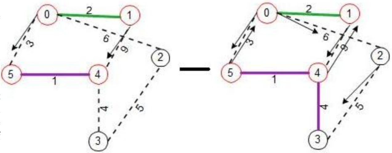
Once the ‘change-core’ message comes to a leaf node where the least weighted edge is present, that node then does a ‘connect’ sending the fragment level as argument. Now node 5 if it was doing its own ‘initiate’ process would know the least weighted edge which in this scenario is also edge (5-0) would do its own connect to node 0. If both nodes do ‘connect’ on the common edge, they would form a higher level fragment.
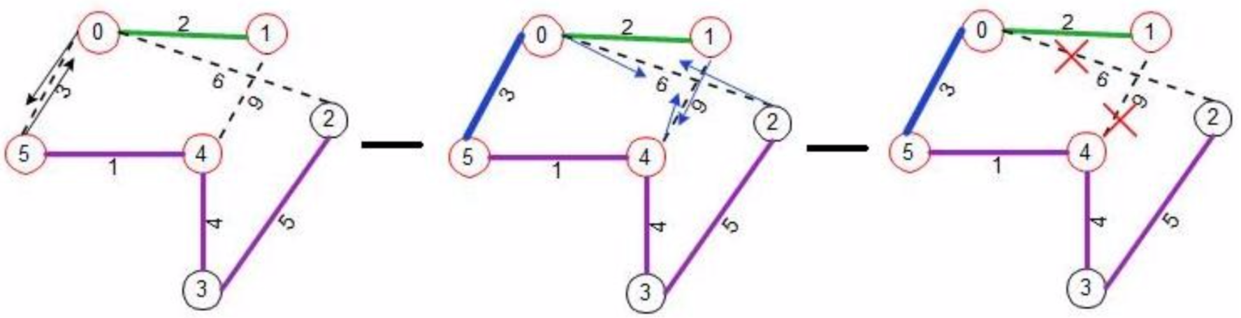
The above pictures shows, nodes 0 and 5 have formed the new ‘core’ edge and the new fragment’s ‘fragment-ID’ changes to 3 and the ‘fragment-level’ is set to 2. Again following the algorithm, nodes 0 and 5 sends ‘initiate’ message with parameters 2, 3 and ‘find’ (‘fragment-level’ and ‘fragment-ID’ and ‘node-state’) to nodes in the outward direction, as and when these ‘initiate’ messages reach other nodes in the fragment, they update their ‘fragment-level’ and ‘fragment-ID’. They also starts sending ‘link-test-probe’ messages on any link that are in ‘basic’ state. Now here ‘link-test-probe’ comes from node 0 to node 2, and if node 2 has not yet received ‘initiate’ message coming from node 5, its level is still 1 and hence it will delay its response in accordance with the algorithm. Node 4 and 1 would send ‘link- test-probe’ on link (1-4) and since their ‘fragment-ID’ is same i.e. 3, they would right away send REJECT and this removes the link (1-4) from the graph.
When ‘initiate’ reaches node 2, it updates its ‘fragment_ID’ and ‘fragment-level’ and now the ‘fragment_ID’ is same as contained in ‘link-test-probe’ it will send back REJECT to node 0, thus removing edge (0-2) from the graph. There remains no outgoing edges to process and the algorithm terminates.
Requirements
This project has three deadlines. An Alpha deadline, Testing deadline, and the Final deadline.
Alpha Requirements
You requirement is the following: the following:
- Choose 1-2 team members. Teams should be between 2-3 people.
- Create a private GitHub repository, each member (and @cegme) should have access.
- Choose a programming language and mandatory project meeting times.
Each member should individually submit answers to questions 1, 2, and 3. Each number is worth 20 points for a total of 60 points. The Alpha deadline is 10/31, 11:59pm.
Testing Requirements
One of the most difficult parts of this project is understanding predicting messages. This is partially because there are so many messages and partially because of the asynchronicity of the messages. To ensure that everyone has a good understanding of the algorithm, we are requiring each group to develop two test cases with unique weights and topologies. In a similar way to what is described in algorithm description, give a starting architecture, node weights, and WakeUp node. Then, walk through the messages that will be passed between nodes until the DMST is found. You will use these test cases in the final project to prove that your code works. Because groups may be across classes, each student must submit a copy of their test description. Please only submit plain text or pdf files.
The total is 200 total points (100 points per test case). Testing deadline is 11/12, 11:59pm.
Project Requirements
All team members must submit the project and also be present during the presentation.
Required files
Please provide all source files as part of your submission. EACH team member must upload EACH file separatley. Do not submit a zip/compressed file.
In addition to all necessary source files, remember to submit you collaboratorfile.
Your README file should contain all information about your project to help the grader run and evaluate your project. Be sure to include (or link to) example of how to run your tests. In there are any bugs, be sure to include describe them.
Presentation description
During “zombie week”, each group will present their working code in class. The professor will grade their assignment at that time. Note the due date for the project is prior to zombie week. Each presentation should essentially include a presentation of the group’s readme contents. Additionally, the group should walk through their two working test cases. The group should also field any questions from the professor or class. Questions may include examination of source code.
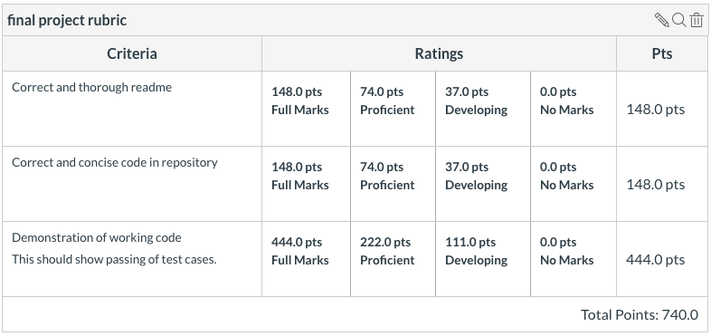
740 total points. Final deadline is 11/26, 11:59pm.
Rubric
Addendum
2019-10-28
- Someone pointed out there is a nice DMST explaination video on YouTube.
Back to projects